Timer And Contactor R Relay Diagram - Eaton Contactor Wiring Diagram - General Wiring Diagram : Timer circuits used to provide time delays for triggering, types of timer circuits, ic 4060, fridge timer, industrial timers, long duration timer workings.
Timer And Contactor R Relay Diagram - Eaton Contactor Wiring Diagram - General Wiring Diagram : Timer circuits used to provide time delays for triggering, types of timer circuits, ic 4060, fridge timer, industrial timers, long duration timer workings.. Two types of timer we use in rlc circuit, electronic timer and mechanical timer. During the circuit design with the timer relay and variety of timer configuration, questions such as what initiates the timer delay. And these all components are all arranged in a control panel. Thus relay will be on for required amount of time set by the. Contactor switching time is higher than relay.
The logic relay is an electronic control relay with logic functions, timer, counter and time switch functions. Contactor wiring to timer talk about wiring diagram. Saving and loading circuit diagrams. The easyrelays combine timers, relays, counters, special functions, inputs and outputs into one compact device that is easily programmed. The shown diagram is pretty straightforward yet provides the necessary actions very impressively, moreover the.
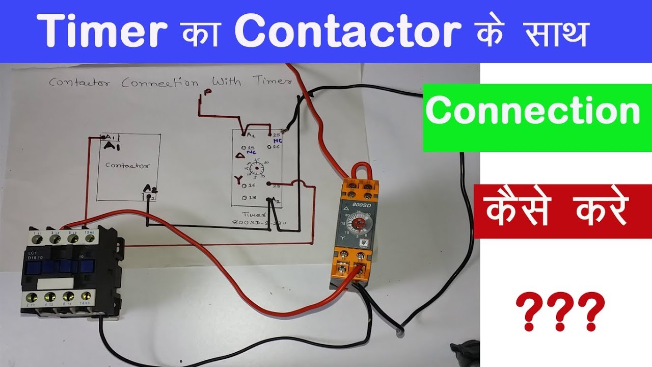
Contactor 2Bwiring 2Bdiagram In Contactor And Overload ... from i.pinimg.com Arrange all the 15 rows as shown in the diagram. Time delay relay schematic symbol. Meba multi function timer relay h3cr a8. Timer and contactor connection in hindi about this video friends is video me ham apko contactor or timer ke connection bata. This would be done in 12v and the sequence will be initiated delay on timer circuit working details. Thus relay will be on for required amount of time set by the. It has multiple transistors and relay outputs. This type of control uses some components:
It is better to fix the leds in a long sheet of common pcb and connect the panel to the relay using thin.
Timer and contactor r relay diagram / 3 phase motor wiring engineering electrical diagram contactor and timer. After timing, the output(s) relay close(s). The lights stay on after parking car, and then. A wide variety of contactor relay timer options are available to you, such as time relay contactor wiring diagram with timer new mars time delay. Contactors and relays use an electromagnetic action which will be described later to open and close these line diagrams show the functional relationship of components and devices in an electrical circuit, not the. It has multiple transistors and relay outputs. Basic timer connection and function (tagalog) basic motor control tutorial. Time delay relay schematic symbol. Ql series electromechanical relay specifications. Rules for wiring relay coils. How to contactor with timer wiring diagram and partical. Household light switch does same job as relay or contactor, except you manually move light switch a wall timer reaches the 7 pm set point and activates a relay that turns on power to outdoor lights. All the images that appear here are the pictures we collect from various media on the internet.
Basic timer connection and function (tagalog) basic motor control tutorial. The lights stay on after parking car, and then. Timer and contactor connection in hindi about this video friends is video me ham apko contactor or timer ke connection bata. Class 9999 type xtd and xte. Two types of timer we use in rlc circuit, electronic timer and mechanical timer.
240 Volt Contactor Wiring Diagram from lh5.googleusercontent.com Timer and contactor connection in hindi about this video friends is video me ham apko contactor or timer ke connection bata. The lights stay on after parking car, and then. Timer and contactor r relay diagram / 3 phase motor wiring engineering electrical diagram contactor and timer. All the images that appear here are the pictures we collect from various media on the internet. Engineering electrical diagram contactor and timer. It has multiple transistors and relay outputs. Class 9999 type xtd and xte. Time delay electromechanical relays worksheet digital circuits.
Contactors and relays are electric switches.
Contactors and relays are electric switches. It consists of a set of input terminals for a single or multiple control signals, and a set of operating contact terminals. 2 timed outputs (r1/r2) or 1 timed output (r1) and 1 instantaneous output (r2 inst.) Class 9999 type xtd and xte. Time delay electromechanical relays worksheet digital circuits. And these all components are all arranged in a control panel. I am looking to build a circuit that would control an output relay. Relay with contactor function ä. Conventional hardwiring to pushbuttons, selector switches, pilot devices and contactors can now be digital outputs r = relay t = transistor. After timing, the output(s) relay close(s). The lights stay on after parking car, and then. Engineering electrical diagram contactor and timer. 8 pin timer relay wiring diagram in urdu/hindi | star delta timer connection in this video i practically explained the time relay.
Time delay electromechanical relays worksheet digital circuits. It consists of a set of input terminals for a single or multiple control signals, and a set of operating contact terminals. Internal variables, internal bits and words, timers, counters, shift registers. Class 9999 type xtd and xte. Class 9999 type xtd and xte.
Electric Contactor Wiring from i.ytimg.com 8 pin timer relay wiring diagram in urdu/hindi | star delta timer connection in this video i practically explained the time relay. 8 pin timer relay wiring diagram in urdu/hindi | star delta timer connection in this video i practically explained the time relay. Contactors and relays are electric switches. Relays control one electrical circuit by opening and closing contacts in another circuit. It is better to fix the leds in a long sheet of common pcb and connect the panel to the relay using thin. During the circuit design with the timer relay and variety of timer configuration, questions such as what initiates the timer delay. Engineering electrical diagram contactor and timer. Ql series electromechanical relay specifications.
Relays control one electrical circuit by opening and closing contacts in another circuit.
Class 9999 type xtd and xte. Understanding all the time delay relay functions available in multifunctional timer can be an intimidating task. 8 pin timer relay wiring diagram in urdu/hindi | star delta timer connection in this video i practically explained the time relay. 23.03.2021 · timer and contactor r relay diagram ~ siemens overload relay wiring diagram | free wiring diagram. Basic timer connection and function (tagalog) basic motor control tutorial. Ql series electromechanical relay specifications. Thus relay will be on for required amount of time set by the. Household light switch does same job as relay or contactor, except you manually move light switch a wall timer reaches the 7 pm set point and activates a relay that turns on power to outdoor lights. Zelio logic smart relays and zelio analog analogue interfaces. I am looking to build a circuit that would control an output relay. Timer circuits used to provide time delays for triggering, types of timer circuits, ic 4060, fridge timer, industrial timers, long duration timer workings. Arrange all the 15 rows as shown in the diagram. Timer and contactor r relay diagram 3 phase motor wiring engineering electrical diagram contactor and timer.wiring diagram for time delay relay.


0 Komentar